Kent Engine Parts
Forged Pistons by CP
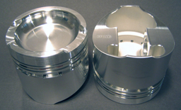 |
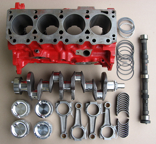
These new forged pistons were developed by Ivey Engines and are made by CP Pistons in California. They are available in standard and .005" oversize. Forged pistons offer much greater reliability and have been referred to as "ten year pistons". In the past, the standard cast Ford and Hepolite pistons had a useful life of one full season in engines run at the National level. |
SCCA / SCAT Crankshaft
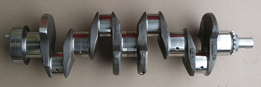
The SCCA/SCAT cast iron crankshaft is a duplicate of the original Uprated Ford OEM unit. This new crankshaft is stronger and comes completely machined and balanced. One item that must be checked is the chamfer on the face of the back where the input shaft splines may need clearance. This crank is available from SCCA Enterprises and from all the major FF engine buildiers.
Connecting Rods
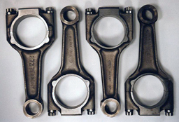 |
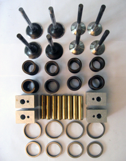
Stock FORD 2737 connecting rods are very sturdy pieces. Properly prepared, they are bulletproof. Preparation includes sizing of big and small ends, lightening, end-to-end balancing and shot peening. Sizing of the big end should be done with the rod bolts in place and fully torqued. Hi-strength 12 point ARP or SPS bolts should be used and torqued to 42 ft/lbs. |
Pierce Aluminum Head
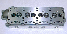 The Pierce aluminum cylinder head is an exact duplicate of the original Ford Uprated cast iron and is finished by CNC machines to assure consistency. This head was produced and approved by the SCCA in the late 1990's when new cast iron heads were no longer available.
There is little or no performance gain to be had but a reduced weight and lower vehicle center of gravity are two benefits. In addition, port prep is easier due to the workability of the aluminum material. This head became "standard equipment" not long after its introduction.
Top End Parts
 |
|
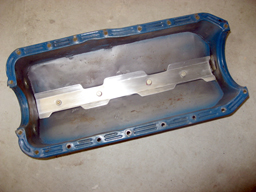
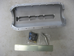
Oil Pan
|
A typical stamped metal KENT engine oil pan modified by adding a valley the full length which is then fitted with a baffle to keep the oil down at the pick-up point. It could be argued that this simple design does everything necessary and that spiffy case pans are overkill! |
 |
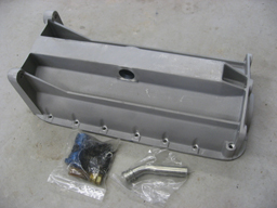
The TITAN cast aluminum pan is a well designed and engineered piece which, like the similar ARE pan made in the US, allows for very efficient pick-up of the oil. It can also add to the structural rigidity of the block and chassis by virtue of its additional mounting holes.
 |
 |
Dry Sump Pumps
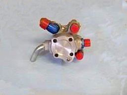 Pictured is a typical five port dry sump oil pump which scavenges oil from the sump and pumps it under pressure through the engine's oil galleries to the main, rod and camshaft bearings. A small amount of oil is also pumped up to the valve gear to lubricate the rockers on the shaft. The galleries also splash oil onto the camshaft and lifters. This five port example sends oil through an oil cooler and filter and then to the sump tank before taking it from the sump tank to send back into the engine. Oil pressure can range from a low of 15 PSI. with hot oil at idle speed up to a maximum of 70 PSI at 7,000 RPM. 50 psi at max RPM is ideal. A pressure adjustment is provided so that the pump pressure can be dialed in. Fittings are typically either BS ( British Standard ) on older pumps or AN10 on newer pumps. Fittings and hoses can be -10 size. "Aeroquip" or "Earl's" braided hoses are spiffy and super rugged but are not at all necessary. High quality rubber hoses are more than adequate.
Typical Engine Installation
 |
This right side picture of the Kent engine installed in a VanDiemen RF98 shows the dry sump pump - in this case with integral oil filter - the Lucas distributor, Weber carburetor and associated throttle linkage along with assorted plumbing, wiring, shift linkage, etc. |
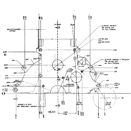
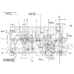
Engine Drawings
 |
 |
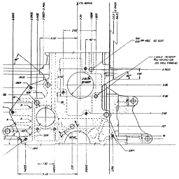 |
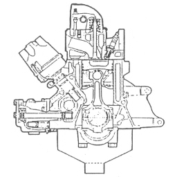 |
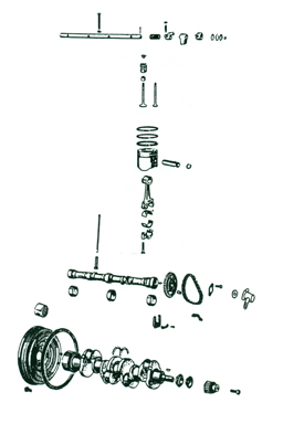
Exploded Engine Diagrams
 |
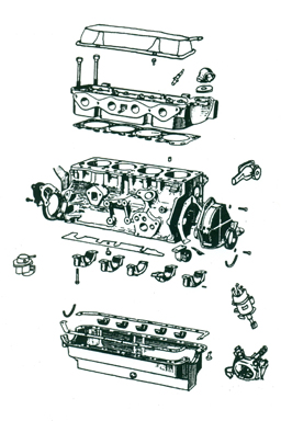 |
| Valve, piston, rod, and rotating assemblies. | Valve cover to pan and everything in between. |
Checking the Compression Ratio
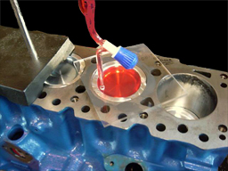 |
Compression ratio is a result of swept cylinder volume compared with volume at Top Dead Center and is affected by piston bowl capacity, cylinder bore, valve protrusion, ring land volume and deck height. This picture shows fluid being measured as it is poured into the cylinder with the piston at TDC. Refer to Jake's book for a very detailed description of this procedure. Oftentimes a homebuilt engine will be set up with a deck height of .010", a dimension which has shown to result in the appropriate compression ratio. |
Explore related content: